TEST ON SCREWLESS TERMINALS
Premier Electrosystem's apparatus are used for testing screwless terminals. These tests are used to check the effect of electric and thermal stress on screwless terminals. Deflection test is used to check the effect of mechanical movement on the screwless terminals. The products are designed as per IS 1293, IS 3854.
Download PDF
ELECTRIC AND THERMAL STRESS SYSTEM
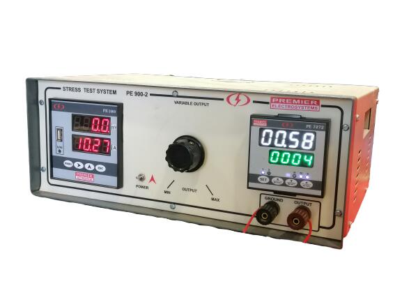
The test apparatus is used to check the effect of electric and thermal stresson the screwless terminal.
The equipment comprises of the follow:
Current Section:
Specified Test current will be passed through the terminal under test
Test Current : 0-30.0 A variable
Display Range : 0-99.9 A
Resolution : 0.1 A
Accuracy : 0.5% ± 1 count
Voltage Section:
The voltage drop across the terminals will be measured.
Range : 0- 99.9 mV
Resolution : 0.1 mV
Accuracy : 0.5% ± 1 count
Timer Section:
To set the duration of Current On and Off time
On Time : 0- 99 min. 59 sec (Preset Value: 30 min 0 sec)
Off Time : 0- 99 min. 59 sec (Preset Value: 30 min 0 sec)
Resolution : 1 sec
Counter Section:
To repeat the On and Off cycle
No of cycles : 0-9999 cycles (Preset Value: 192)
Resolution : 1 count
Data Logging Section:
To log the voltage drop occurred at specified time
Parameters Logged : Date, Time, Voltage
Log rate : 1 hr to 50 hours (Preset: 24 hrs)
Log System : Direct into pen drive
View Data : Direct view on PC
Power Supply : 230 V ± 10%, 50 Hz
Material : MS panel duly painted to avoid rust
Indication : Names of all meter and LEDs where required
Safety : Master On/ Off Switch
Calibration : NABL
DEFLECTION TEST
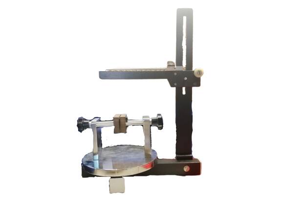
Deflection Test on Screwless Terminal is used to check the effect of load and rotation on screwless terminals.
Current Section:
Specified Test current will be passed through the terminal under test
Test Current : 0-30.0 A variable
Resolution : 0.1 A
Accuracy : 0.5% ± 1 count
Current variation : Within 5% using suitable resistance
Voltage Section:
The voltage drop across the terminals will be measured.
Range : 0- 99.9 mV
Resolution : 0.1 mV
Accuracy : 0.5% ± 1 count
Mechanical Assembly:
The mechanical assembly will have the following facilities:
* To mount the terminal under test to the test area
* To insert and remove the conductor of the suitable length and cross section for sequence change
* To clamp the points at which the voltage drop is to be measured.
* To apply load of 0.25 N, 0.5 N, 1 N through weights.
* Mount on different holes the entire assembly to check the voltage drop at 12 directions, differing through 30 degree
Panel:
To mount all above units in a single assembly
Power Supply : 230 V ± 10%, 50 Hz
Material : MS panel duly painted to avoid rust
Calibration : NABL
Download PDF
Other Relevant Products:
Earth Contact Resistance Tester- Click here
HV Tester-Click here
Cutout Tester- Click here